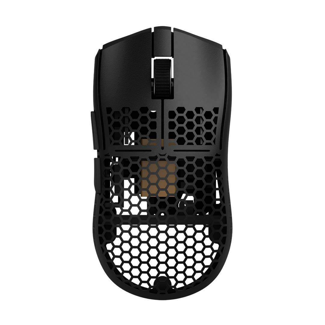

 Top shell, bottom shell, 2x clips, magnetic adapter, AAA USB battery, mouse feet, redrill screwholes if needed: Bottom 4 screw holes are 1.8mm, all other ones are 1.3mm. Top shell, bottom shell, 2x clips, magnetic adapter, AAA USB battery, mouse feet, redrill screwholes if needed: Bottom 4 screw holes are 1.8mm, all other ones are 1.3mm.
|
 Small screwdriver: Known as Phillips screwdriver Small screwdriver: Known as Phillips screwdriver |
|
The recent MOD-KITs came with the hot swap PCBs. Simply push the Kailh 4.0 in the PCBs in the correct orientation. [ Depending on the version and production quality of the G305 PCB, the tubes of the hot-swap PCBs might not fit through the G305 PCB very well. Filing the holes or using the screwdriver to increase their diameter or using a decent amount of force might be needed. ] |

 From left to right: Bottom screws, side button screw, mid screws, switch screws From left to right: Bottom screws, side button screw, mid screws, switch screws(Save the small screws for the end!)
|
 Pay attention to the orientation! |
|
|
 Stop tightening them once the screw heads touch the PCB. They cut their own thread and we don't wanna destroy it by over-tightening the screws!
|
|
 Insert the mouse wheel in the encoder and add the small spring. Make sure the small spring sits in the small grooves
 |
 Take care not to over-tighten the screws!
|
 Give them a bit of curvature Give them a bit of curvature |
 |
 |
|
|

 |
 |
 Pay attention to the orientation of the pins Pay attention to the orientation of the pins |
 |
 |
 Pay attention to the battery's orientation!
|
 |
 You will need more force than you think. Check if the battery is charging before you continue.
|
 Plug in battery cable, pay attention to it's orientation! |
 Add large screws at the bottom (or on the sides with newer versions) Add large screws at the bottom (or on the sides with newer versions) |
 |
 |
 Add mouse feet to your mouse as shown in the picture
|

Download Link to Onboard Memory Managment from the official Logitech Support site. Make sure to set the report rate to 1000. If you encounter issues with this software, try this one instead.
|
Check out further instructions here.
For calibration instructions, click here.
|
Enjoy gaming. |
If there are any questions feel free to contact us.