



STEP 1: PREPARATION & SWITCH INSTALLATION
We recommend watching a step, then assembling that step right after.
- Check the buttons. If there is no movement there might be a printing support blocking the button.
- Add a spacer to each plunger using the tweezers.
- Add switches with the big head screws. There should not be a gap between shell and switch.
- Check the clicks.
Pre-travel Adjustment:
To reduce pre-travel, add a spacer to the plunger.
To increase pre-travel:
- Remove the spacer from the plunger, or
- Loosen the switch screws by ¼ or ½ turn.
A ¼ turn makes a smaller adjustment, while a ½ turn increases the pre-travel further.

STEP 1
STEP 2: ADD SIDE BUTTON PCB
- Before you watch the video: Bend the cables in the direction of the switches and let it exit towards the back like shown on the photo below. This method is better than the one in the video since it avoids any damage to the cables.
- Insert the side button PCB in the side button holder and secure the PCB with the big head screws.
- Check the clicks.
Note: If you experience any problems write to support@pmm.gg
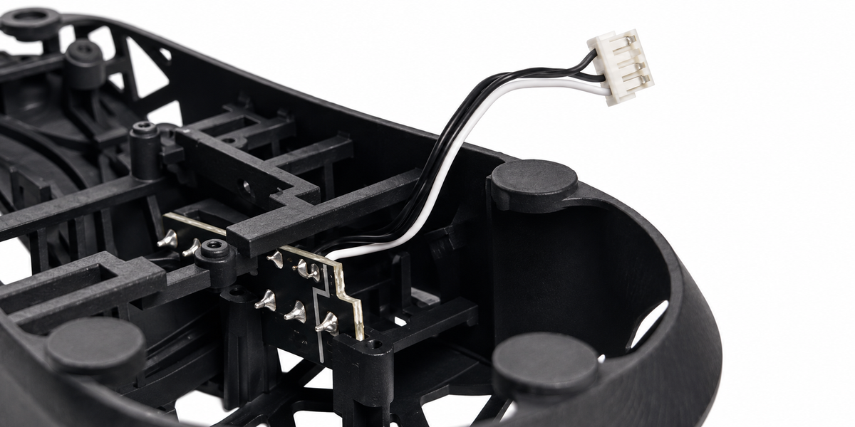
Alternative option to add the side button PCB.

STEP 3: ADD ULTRAFLAT SYSTEM SCREWS

STEP 4: ADD CABLE
Add the cable support and insert it in the holder in the front. The opening should face upwards.
Note: We recommend updating the OP1 8K firmware using the stock cable.

STEP 3.1
STEP 5: ADD CARBON FIBER RODS
- Start with the front carbon fiber rod on the side with the side buttons. The fit may be very tight. To insert the rod into the holder on the side-button side, gently push the shell toward the opposite side to create a little more space. Once the rod is seated correctly in the holder on the side-button side, press the other end down until it snaps into the holder on the opposite side.
- For the second rod, the installation works in reverse. Start by placing the rod into the holder on the opposite side. If the fit is too tight, use the rod holder itself or a pry tool to gently push the rod toward the other side until it can fully seat in the holder. Once it is in place, snap the other end into the holder on the side-button side.

STEP 6.1: ADD THE MAIN PCB

STEP 6.2: ADD THE MAIN PCB

STEP 7: ADD LOD ADAPTER
- Use long screws to fasten the adapter onto the shell.

STEP 8: ADD THE SKATES & FINAL CHECK
Your Mod-kit should come with our dot skates but you can also use any other dot skates.
