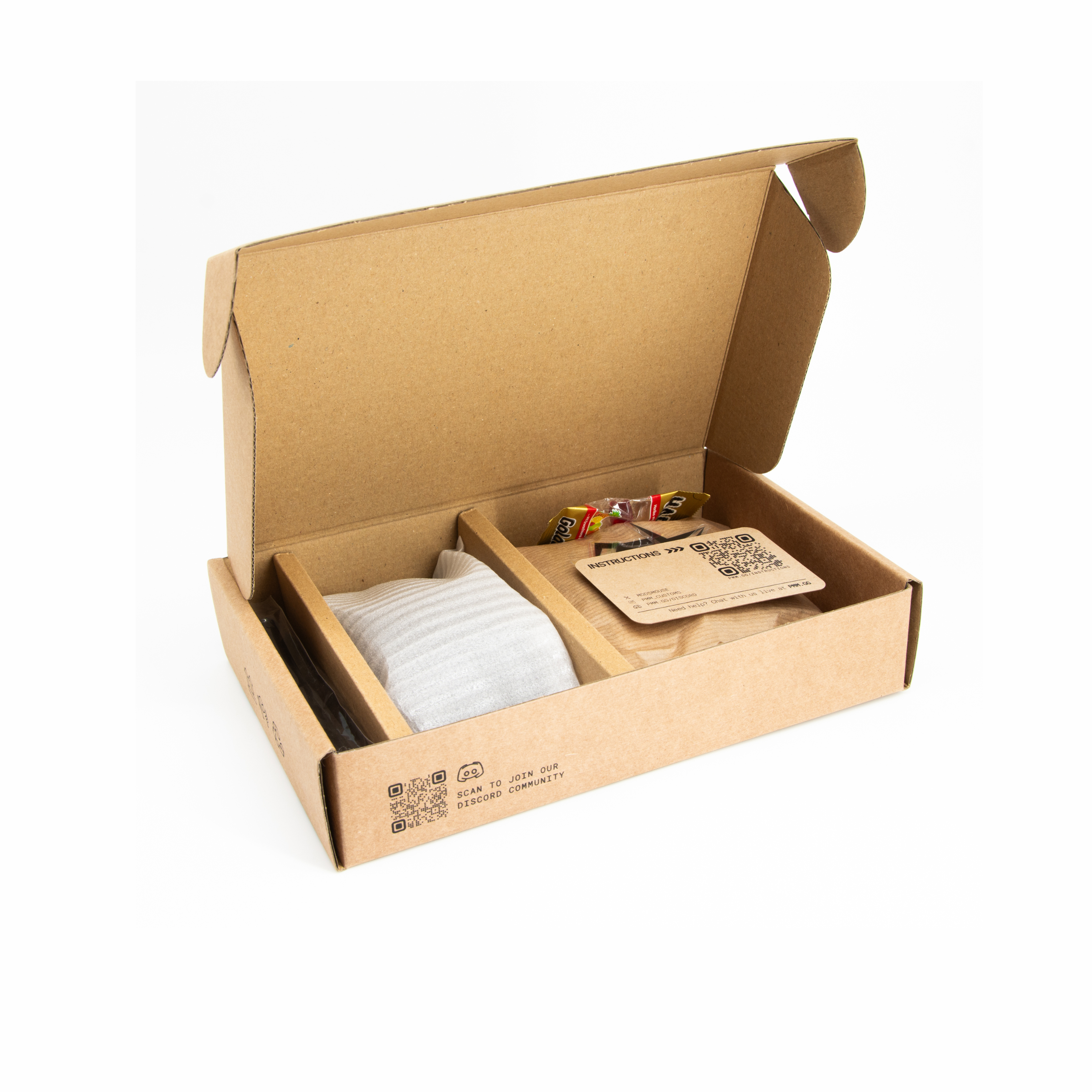
Instructions
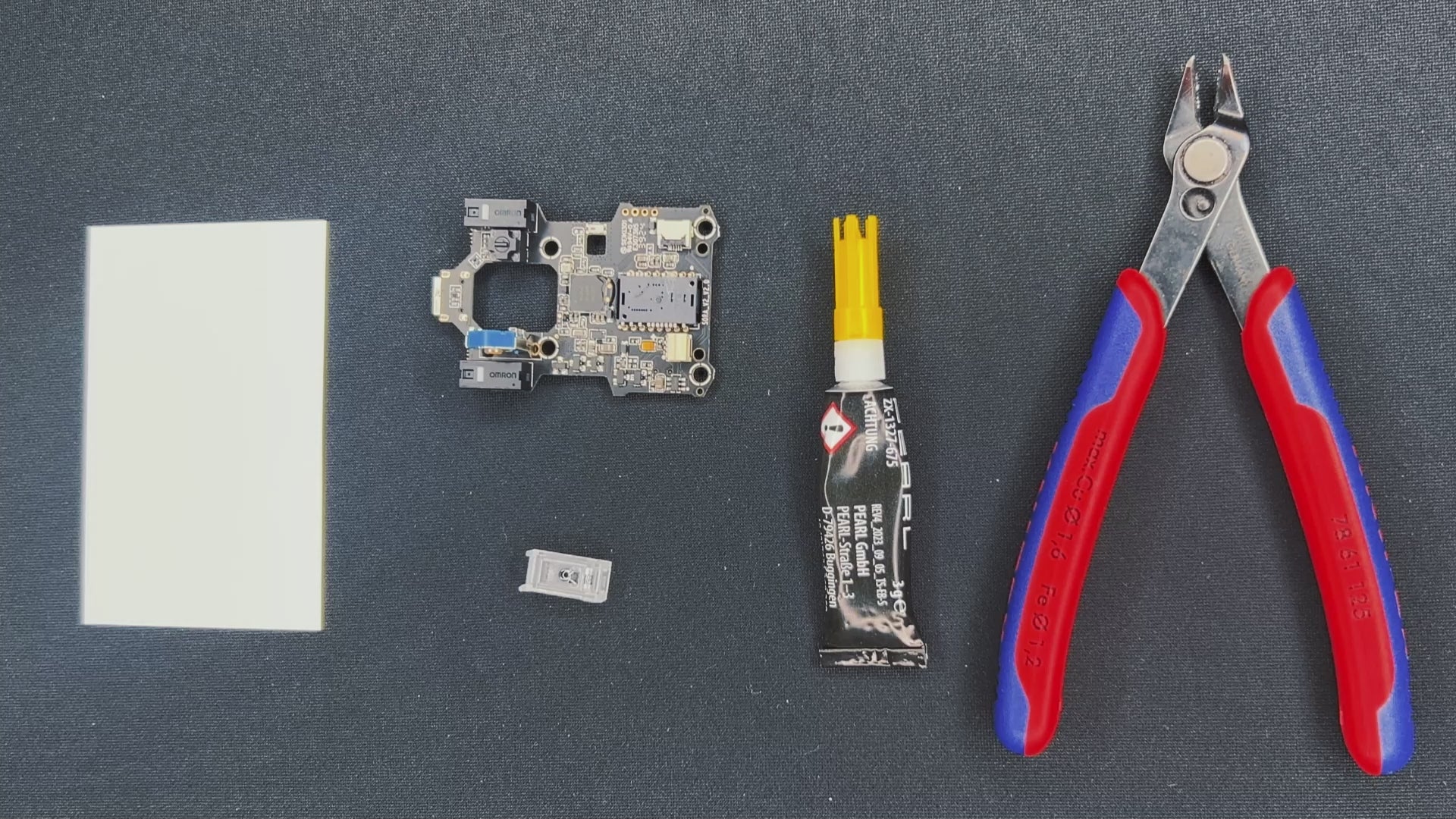
STEP 1: PREPARATION
Glue the sensor lens to the PCB
- Put a drop of super glue on a sheet of e.g. paper and dip all 4 pins of the lens into it. Do not use too much glue.
- Add the sensor to the PCB. Wait for 5 mins until glue is fully dry.
- Cut the two pins, so the battery can be placed on the sensor.
STEP 1
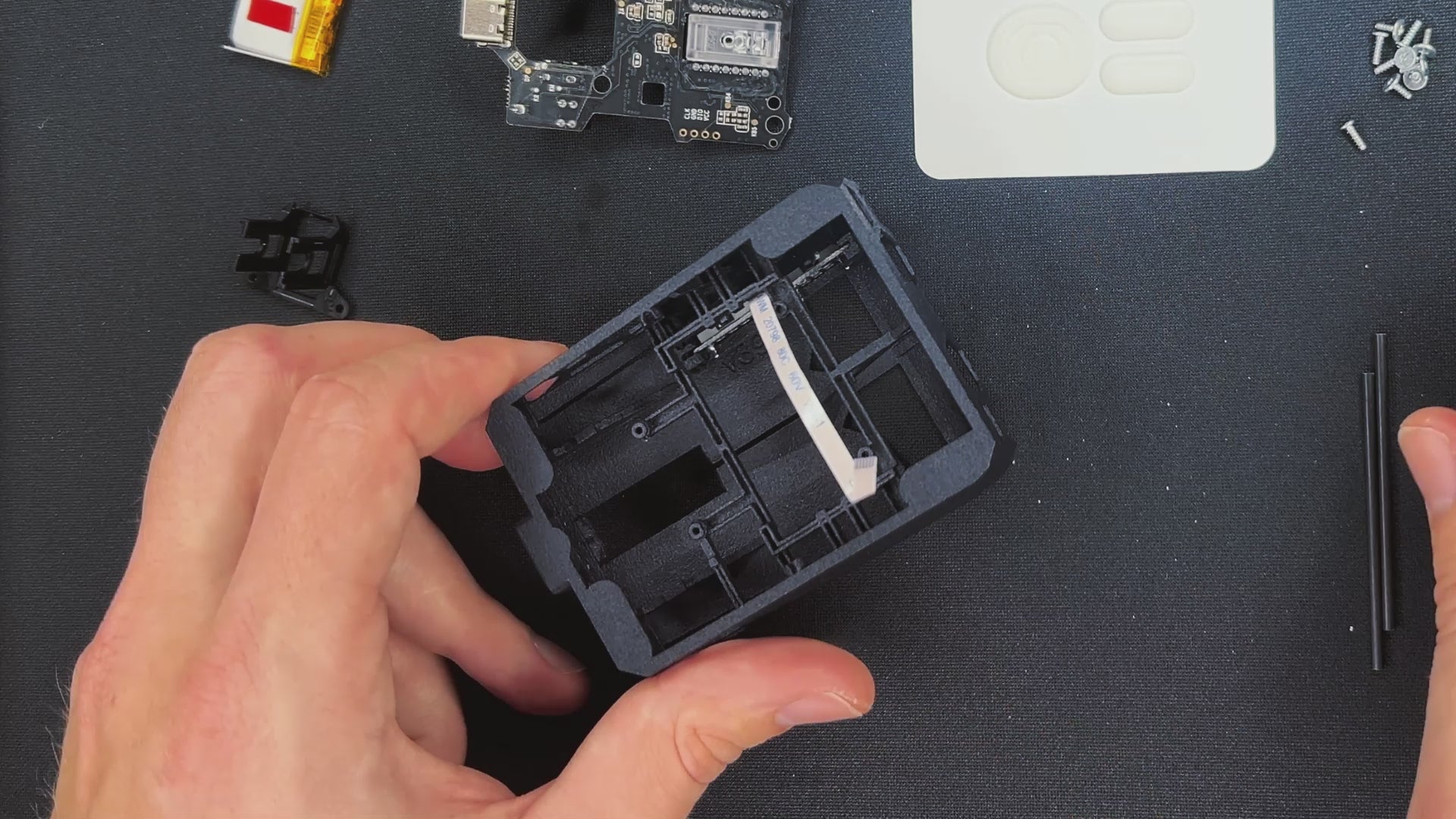
STEP 2: ADD THE SIDE BUTTON PCB
- Make sure the side button PCB is connected to the cable.
- Use the screwdriver or tweezers to put the PCB into place.
- The metal pins of the side button PCBs have to go under the small hooks on both sides.
STEP 2
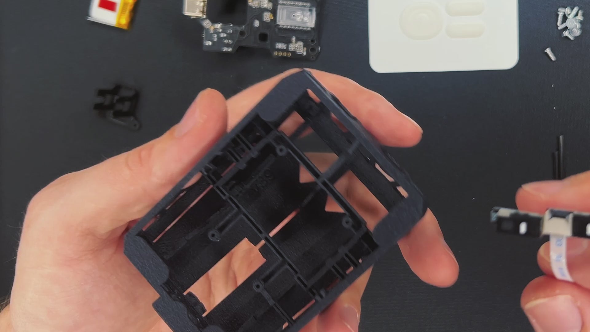
STEP 3: INSTALL CARBON FIBER ROD
If you are using only one carbon fiber rod, we recommend placing it here.
- Start with locating the two spots designated for the rod. You can see on the side with side buttons, the opening of the rod holder is a little bigger so you can click the rod in.
- First, insert the rod into the closed rod holder. then try to click it in on the side of the side buttons. Don't push to hard.
STEP 3
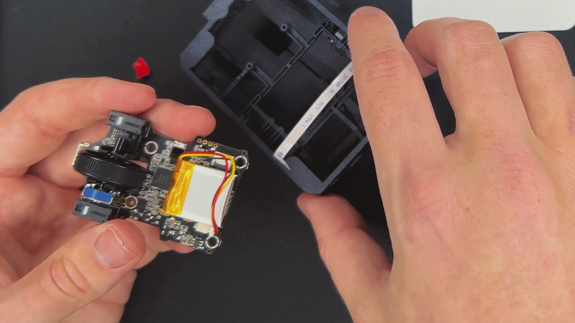
STEP 4: ADD THE BATTERY
NOTE: You can also use the mouse wired. In that case you don`t need to attach the battery. It will save you 3g.
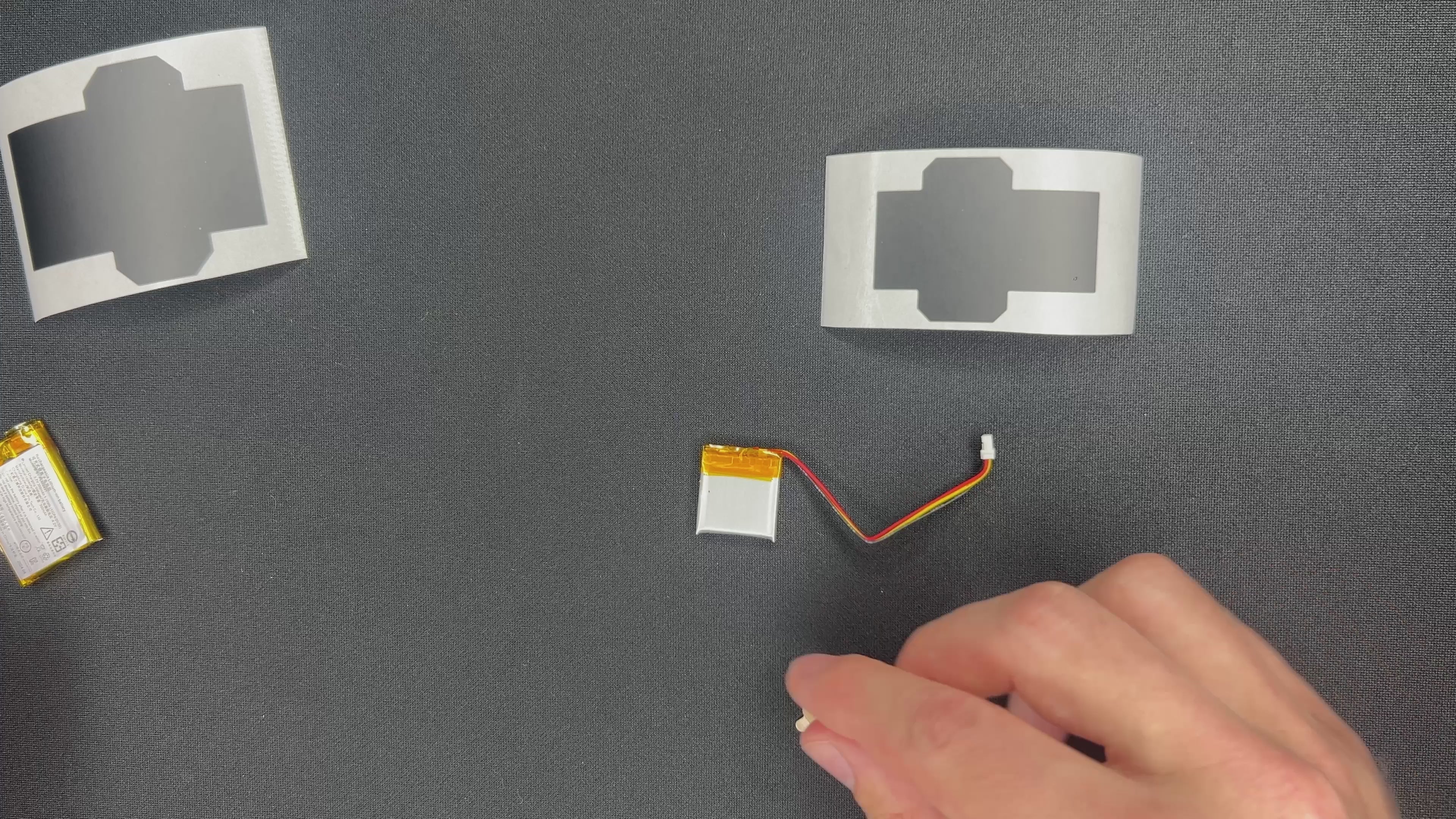
Battery wrapping
- Place the battery in the back of the PCB as seen in the video. It should not extend the PCB.
- Check the battery cable. There is only one way to plug in the cable. Check that the connectors are in the correct direction.
STEP 4
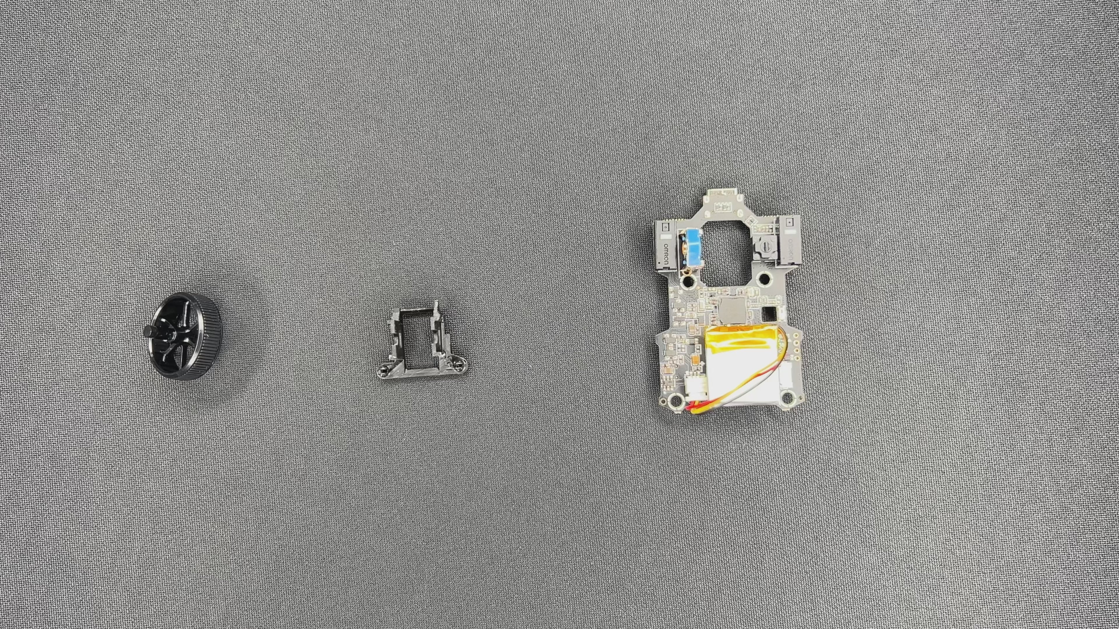
STEP 5: INSTALL THE MOUSE WHEEL HOLDER
1. Add the mouse wheel holder by clipping it into the PCB.
2. Insert the mouse wheel by slightly pushing the encoder to the side.
3. Center the mouse wheel and check if it spins freely and the M3 click works well
Note: If the mouse wheel turns with too much resistance, some sanding of the holder might be required.
STEP 5
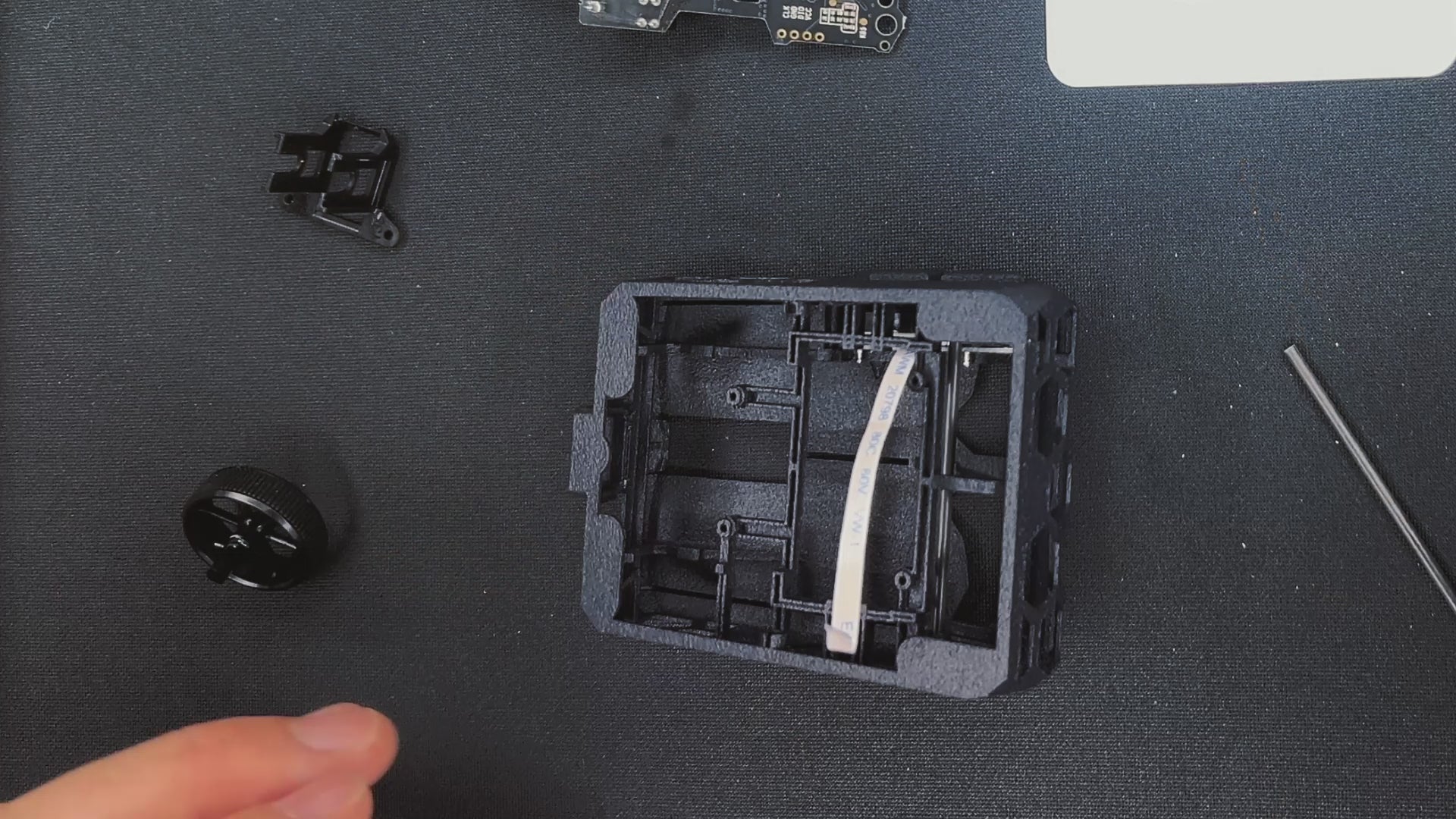
STEP 6: CONNECT THE SIDE BUTTON PCB WITH MAIN PCB
- Open the connector on the main PCB.
- Insert the cable.
- Close the cable lock. You might need a screwdriver, be careful.
STEP 6
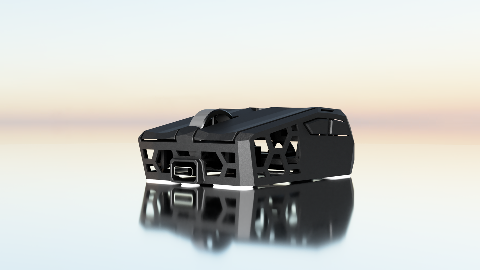
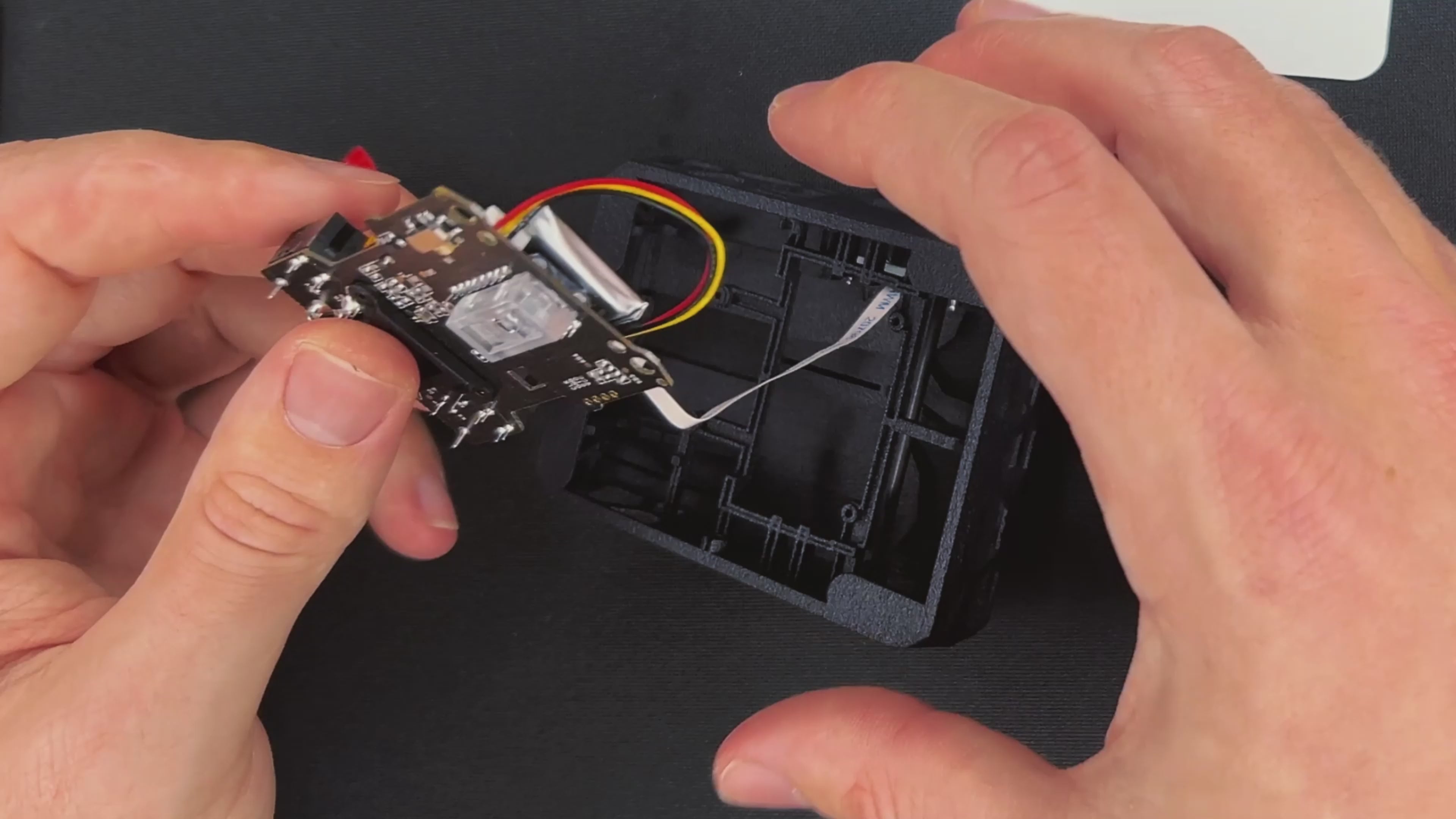
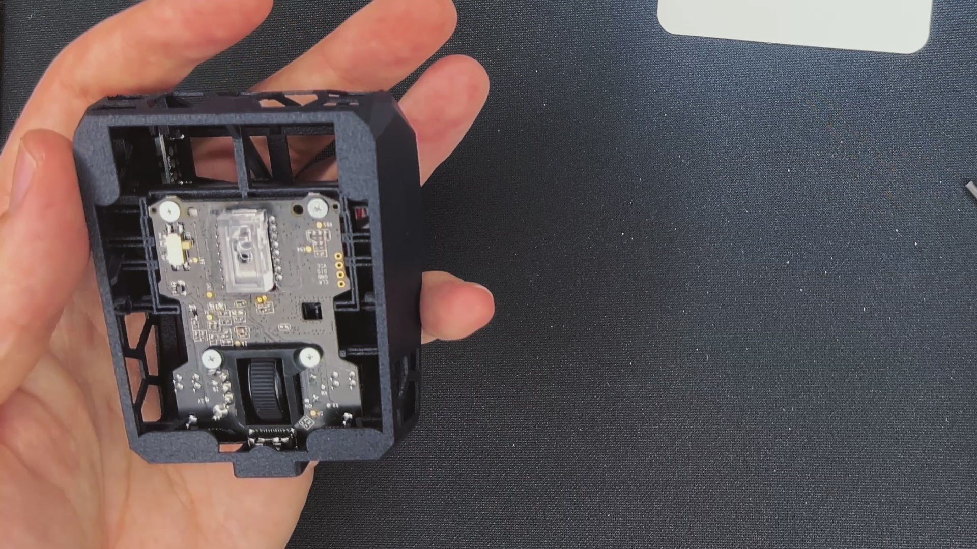
STEP 7: ADD THE PCB TO THE SHELL
- Start with placing the USB-C socket in the charger hole.
- Bring the PCB under the hooks in the front.
- Slowly go around the edges and place the PCB in the frame.
- Use your screwdriver to further insert the PCB.
- Check if the clicks work.
- Screw the PCB to the shell.
STEP 7
STEP 8: INSTALL THE MAIN PCB
- Install the second rod. Same principle.
- Place the mouse feet on the designated spots.
- If you are using dots or sapphire skates we recommend to place 5 skates on the mouse. Three in the front and 2 in the back.
STEP 9
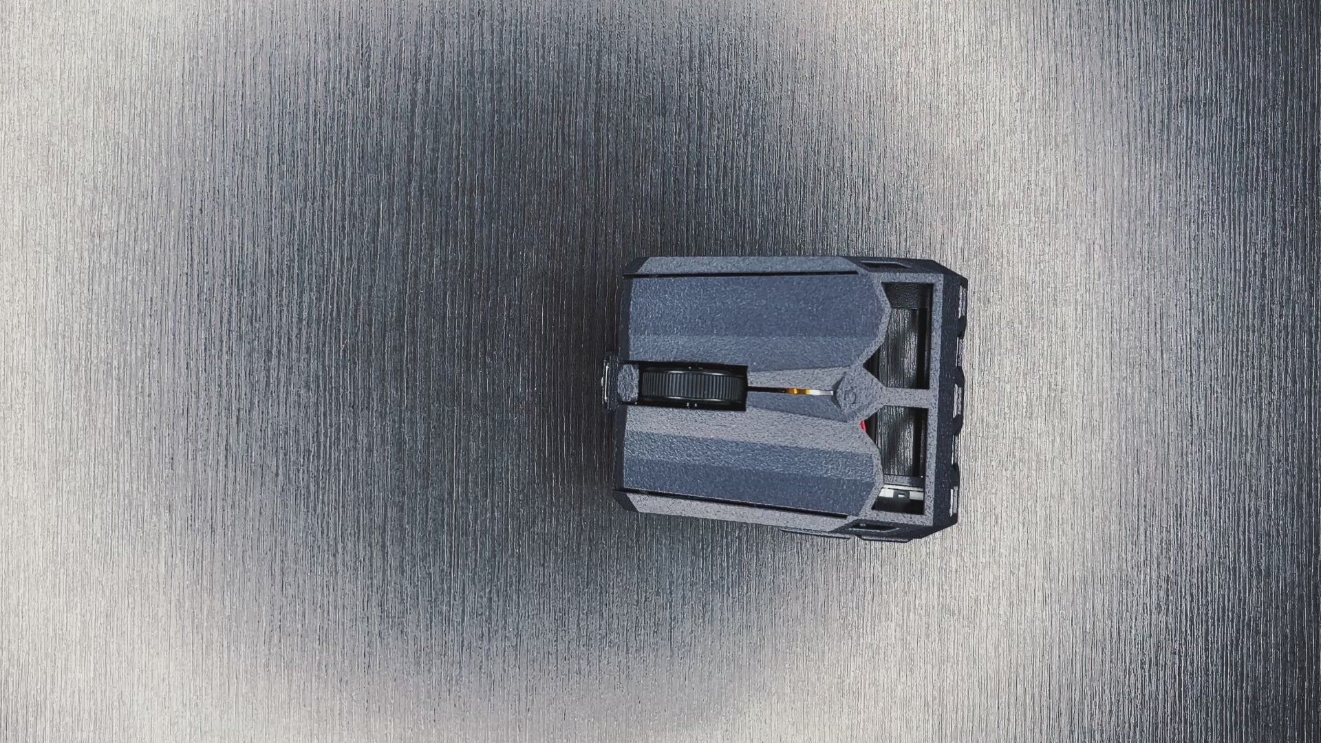
STEP 9: FINAL CHECK
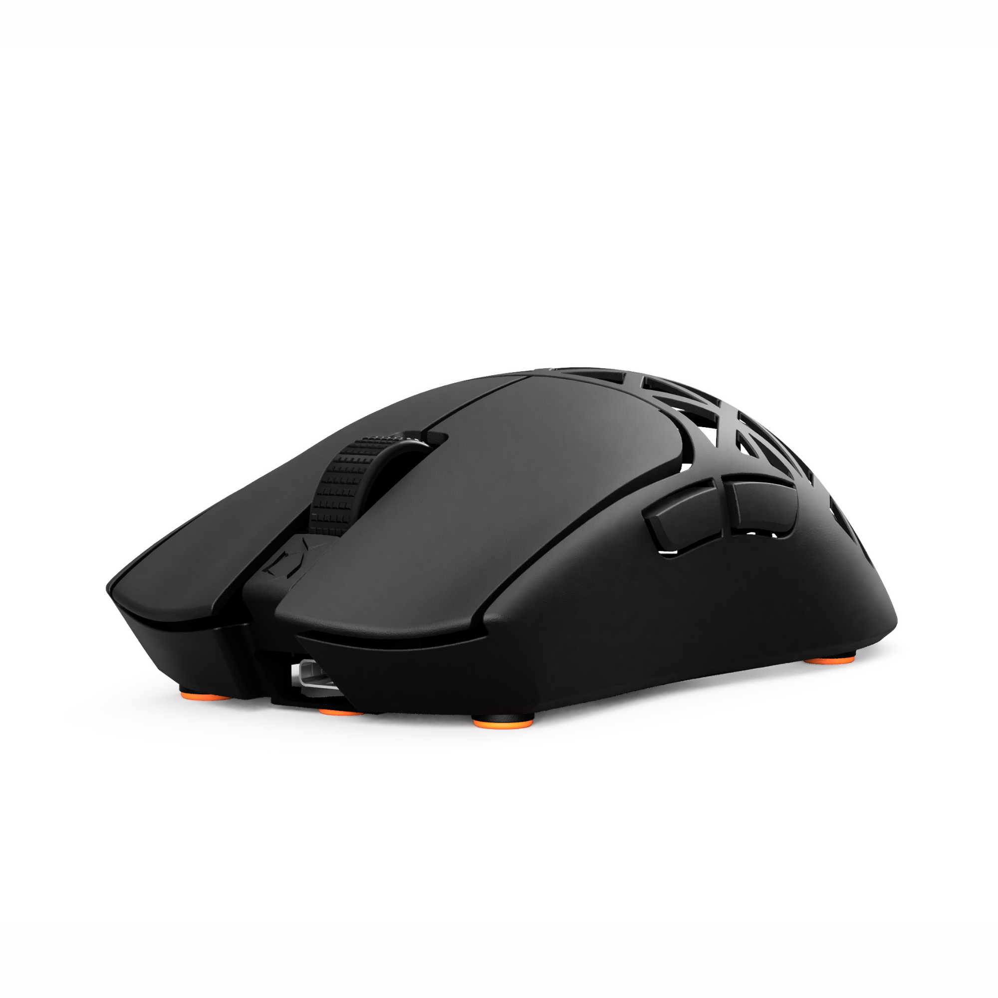
To turn on the mouse, you need to move the white knob (bottom right) towards the mouse wheel.
Check if all mouse skates touch the ground. If that is not the case it is possible that the PCB got slightly bent during the disassembly process. To fix this problem you need to bend the shell in the opposite direction. You can keep the mouse assembled during this step. Repeat the process until all mouse skates are on the ground. If the scroll wheel feels too tight contact our support team at support@pmm.gg
Change LOD, DPI and button bindings here
STEP 10
YOU DID IT!
Well done.